The intended use for Diamond Pier DP-50 and DP-75 foundations sold through retail stores is to support simple residential projects constructed with columns, posts, and beams. The scope of project is defined as decks, covered decks, walkways, stairways, and accessory structures or similar projects that meet this intent. The International Residential Code (IRC) defines an accessory structure as a structure that is accessory to and incidental to that of the dwelling(s) and that is located on the same lot. Projects using Diamond Pier foundations must be less than 600 square feet.
See table below.
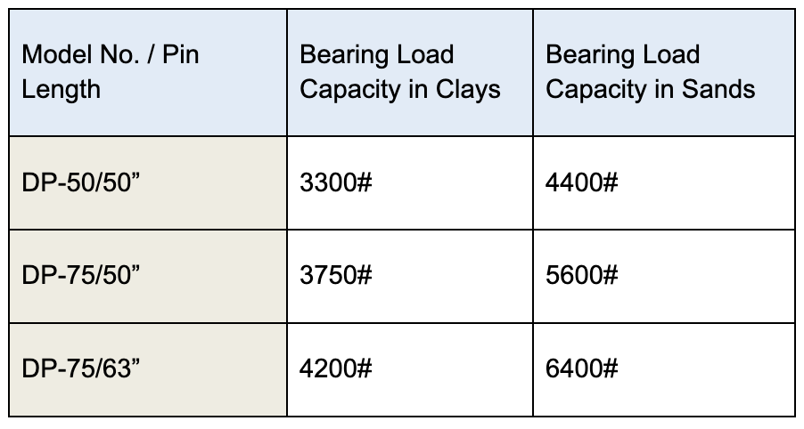
For more information, please reference the “Residential Diamond Pier Load Chart” (found at www.diamondpiers.com).
Over a 10-year period, Diamond Pier foundations have resisted the effects of frost heave in 99.7% of footing installations in the study area discussed in this document, which covers Minnesota and portions of neighboring states in the Northern Midwest.
Secure your permit prior to purchase. For Diamond Pier foundations, the procedure is to submit the Diamond Pier product as an alternate method with the application for the building permit. This is accomplished by attaching a detail of the Diamond Pier product in the project drawings, along with the layout and spacing of the piers in accordance with the “Residential Diamond Pier Load Chart.” Also, it is important to include a current copy of ICC-ES evaluation reports ESR-1895 and EER-1895 and, if requested, frost performance documents, all of which are available at www.diamondpiers.com.
Secure your permit prior to purchase. Yes, the Diamond Pier precast concrete pier foundation assembly (Models DP-50 and DP-75) has been evaluated and approved for use as a foundation for the support of gravity loads, as well as specified lateral and uplift loads, for exterior decks, covered enclosed porches, and sunrooms as defined in the 2018 IRC R301.2.1.1.1, Categories I through IV, elevated walkways and stairways as regulated by the current Wisconsin Uniform Dwelling Code (UDC) and some site accessory detached structures not directly covered by the UDC rules. This approval is not for support of habitable enclosed dwelling areas. This approval is for installation of these footings per the manufacturer’s installation manual to support/resist loads as tested and published with the adjustments as noted in the “Wisconsin UDC Approval”, which can be downloaded from the website (www.diamondpiers.com/downloadable-documents).
Read and follow the installation instructions in the Diamond Pier Installation Manual, which can be downloaded from the website (www.diamondpiers.com/downloadable-documents).
For DP-50/50 and DP 75/63 please visit our Retail Locator on our website to find a retailer near you. For larger piers for engineered projects please contact PFI.
The Diamond Pier system is intended for simple structures supported by columns, posts, and beams loaded up to, but not exceeding, the stated capacities for bearing, uplift, and lateral loads on the “Residential Diamond Pier Load Chart.” It is not intended for structures with asymmetrical, rotational, overturning, or dynamic forces. Intended uses are described in section 2.0 of ICC-ES prescriptive bearing evaluation report ESR-1895. For projects that exceed the capacities or limitations defined herein, or the intended uses described in ESR-1895, contact Pin Foundations, Inc. (PFI) for additional information or site-specific capacity evaluation.
Inspect your Diamond Pier assemblies to ensure that no parts are flawed or have been damaged in shipping. Do not install a concrete pier if it has a structural crack. A structural crack is a fissure running internally into the head. It is perpendicular to the outer face of the head and runs inward to its core. This can weaken the strength of the pier head and/or allow water to penetrate and cause freeze/thaw problems in the concrete. Slight flaking or chipping on delivery or after installation is acceptable damage. If a concrete head has a structural crack, it should NOT be patched. It must be removed and replaced.
Download the Limited Lifetime Warranty Application Form available at https://www.diamondpiers.com/installation-manual/register-product-warranty. Complete and submit the application within 30 days of project completion. Be sure to confirm receipt of your registered warranty by PFI.
Yes, but consider the possibility of the traditional pier heaving. We have seen cases where the traditional concrete pier heaved and the Diamond Pier head held, which created opposing forces.
Diamond Pier foundations sold through retail outlets are intended for use on a residential property. Typically, when a home is built, the soils are analyzed and recorded with the building department. Check with your local building department regarding presumptive soil values. Supporting soils that do not meet the presumptive soil strength defined in the applicable code will be communicated to you by your building department, in which case the bearing capacity may need to be determined by a soils investigation.
If the presumptive soil capacity cannot be assumed in accordance with the IRC Table R401.4.1 (Presumptive Load-Bearing Values of Foundation Materials), the code official may request a soils report. This would apply to any foundation, not just Diamond Pier foundations. If the code official is allowing any other foundation types to be installed without a soils report, then the code official is utilizing presumptive soils values and should apply those values for the Diamond Pier foundation.
Some soils may not be appropriate for supporting Diamond Pier foundations. Examples include soils that are weaker than 1500 psf, soils that are highly expansive, shifting or sliding soils, soils on slopes greater than 2:1 (27 degrees), contaminated soils, or soils where traditional concrete piers, accepted by local codes, are unable to provide adequate bearing to support the loads of the project or to protect the structure from the negative effects of frost heave. Where unsound soils exist, a registered design professional may be required to review the project.
Water is not the concern. The Diamond Pier footings may sit in water/wet conditions. The concern is the effect the presence of water may have on the strength of the soil. Soils can be weakened when they retain standing water or are improperly drained, and in certain types of soil this can also cause heave problems. A site depression with standing water or the potential for water to pond, pool, or saturate the soil may be an indication that the soil is not sound. Downspouts that discharge at or near a foundation may also cause soil problems, and setting a Diamond Pier foundation adjacent to any water body should be considered carefully. Depending on the variables involved, soils at the edge of or within lakes, ponds, rivers, streams, or tidal zones may be considerably weaker (as much as 40% or more) than dry or well-drained soils. Also, soils adjacent to existing foundations may have been improperly or loosely backfilled, which could cause poor drainage or poor soil conditions. Be sure to inform your project designer if any of these conditions exist.
Rather than reaching a specific vertical depth or gross weight, Diamond Pier foundations resist heave pressures with their wide-spreading pin pile groups. Embedded in the intact soil structure, the pins are prevented from changing angle under load by the concrete head, creating a stable foundation for both bearing and uplift forces. Because of the unique design of the Diamond Pier head, the pins are also free to move along their axes without compromising the position of the head or its lock on the pin cluster. This feature allows the Diamond Pier foundation to absorb soil strains caused by frost heave or expansive conditions without losing alignment or transferring these strains to the supported structure.
When assessing projects in extreme frost areas, be aware of sites where traditional concrete footings— 48" to 60" deep—have failed to resist frost heave, requiring larger, deeper concrete piers. Project sites that require concrete footings deeper than 60" to resist frost heave exceed the definition of normal soil conditions and the limits of a Diamond Pier footing as specified on the “Residential Diamond Pier Load Chart.”
You will need to assemble the following tools and gear:
- Automatic driving hammer with 1-1/8" hex shaft driving bit
- Square-edge shovel
- Sledgehammer
- Torpedo level
- Tape measure
- Pipe wrench
- Proper protective gear, including safety goggles, ear protection, insulated gloves, protective clothing, and boots
We recommend a minimum two-person crew for installation.
Any standard automatic hammer that will handle a 1-1/8" hex shaft can be used, provided it can be properly and safely controlled by the operator and not risk injury or damage to the concrete head. Soft or loose soils will allow for the use of lighter lower-energy hammers. Stiff or dense soils will require electric hammers in the higher impact range or standard jackhammers driven by compressed air. In most cases, the DP-50 and DP-75 are installed with electric hammers. Roto-hammers are not adequate.
All underground utility lines must be located and properly marked by your local official utility locating service, and all privately run lines must also be identified and located by the proper authority. If there are any electrical lines in the area, de-energize the power source prior to installing the Diamond Pier foundations. Never allow bodily contact with uninsulated portions of the automatic breaker hammer. Wear properly rated rubber-insulated gloves and boots. In addition, if underground utilities are located on the site, check with your local utility locating service to confirm required safety zones. You must ensure that the horizontal pin distance for your foundation will have adequate horizontal clearance to be well outside all safety zones, including the 6" Diamond Pier (DP) Safety Zone (see Figure 2 and Table 2 on page 9 of the Diamond Pier Installation Manual). Do not install Diamond Pier foundations before all underground utilities have been located, marked, and de-energized.
To meet the load bearing capacities shown in the “Residential Diamond Pier Load Chart,” Diamond Pier foundations must be spaced a minimum of 3 feet apart (from center of pier anchor bolt to center of pier anchor bolt). If they are spaced less than 3 feet apart, the bearing capacity must be reduced by 13% for each closer-spaced pier.
The Diamond Pier must be set in properly compacted soils, meeting the minimum requirement of 1500 psf. The piers must also be set back in the correct horizontal distance from existing foundations or other buried obstacles, as shown in Table 2 on page 9 of the Diamond Pier Installation Manual. Tributary loads from the supported structure must be properly calculated, and the piers spaced accordingly, so that each pier is supporting only up to its designated allowable load.
The concrete head may also be buried for aesthetic considerations, but access to the top of the head needs to be maintained. Concrete slabs, patios, and other products already installed or to be installed MUST NOT interfere with the Diamond Pier foundation and the attached post/beam assembly. Expansion joints may be used to protect the foundation. Proper drainage must also be maintained.
If close to the surface, you can either dig up the obstruction and remove it, drive the pin past or through it, remove the soil plug and attempt to redrive it (requires building official approval), or remove the pins and realign the concrete head.
The jacking method is used to spin and pry a pin out from the concrete head simultaneously by using a pipe wrench and a pry bar. This method works best when the pin is approximately 6" extended out from the concrete head. A pipe wrench, a flat bar, and a pry bar are required. Follow the instructions below to turn the pin while corkscrewing it upward. See also the pin removal video on the website (Removing Diamond Pier Foundations at https://www.diamondpiers.com/videos).
- Using your right hand, place the pry bar flat against the concrete angle at the outer edge of the pier head and perpendicular to the pin to be removed.
- With your left hand, place the pipe wrench on the pin and slide it down tight to the pry bar. The pipe wrench handle should be pointing up slightly and perpendicular to the pry bar to allow the pipe wrench to turn the pin as it is pried (see Figure 8 in the Diamond Pier Installation Manual).
- Pull up on the pipe wrench handle to lock.
- Pull up on the pry bar with your right hand to move the pin out approximately 1" to 2".
- Slide the pry bar back to be flush with the concrete angle on the pier head.
Repeat lock and jack (steps 3–5) until the pin can be pulled out by hand.
Check your local building code or building official to verify which post bases are acceptable in your area, and make sure to match the post size and loads on the post with the appropriate bracket size and bracket load ratings. Typically, these brackets come with a “standoff” design that separates the wood from contact with the base of the bracket and eliminates the need to drill into the bottom of the lumber to compensate for the raised anchor bolt. Most post-base brackets have a wide hole in the base that allows for horizontal adjustment of the final bracket location.
A Diamond Pier foundation code inspection may take place at any time during or after installation and may be combined with the structural framing inspection as each jurisdiction warrants. The top ends of all pins need to be accessible for measuring pin lengths. If the project is low to the ground, make sure the inspection is done prior to installing the flooring.
Check with the local building code for criteria or limitations on installing foundations in frozen soil. The soil will need to be thawed prior to installation.
The ICC-ES Equivalency Evaluation Report (IRC) EER-1895 addresses only conformance with the IRC sections noted below. For projects outside this equivalency evaluation subject in EER-1895, contact PFI for site-specific engineering.
PFI provides ICC-ES evaluation reports ESR-1895 and EER-1895 and the Wisconsin UDC Product Approval form 201612-O as evidence of code compliance. These code documents provide evidence of compliance for the DP-50 and DP-75 models when used for projects that meet the intent defined in ESR-1895 section 2.0 as decks, covered decks, walkways, stairways, and accessory structures. For municipalities that are not governed under the IRC structure, PFI provides the evaluation service report, state or municipal product certifications, or third-party testing reports as satisfactory evidence of compliance for your building code official.