How It Works
Understanding Diamond Pier & Pin Pile Technology
Pin Foundations, Inc., manufacturer of the Diamond Pier, has been designing and manufacturing foundations for over 30 years. One thing has always driven our thinking; The Earth is the actual foundation, and soils, in their natural undisturbed state, have the strength and structure to do the job.
That's why the Diamond Pier is based on Pin Pile Technology. Pilings keep the Earth’s existing soil strength and structure intact, and are easy to install if they do not need to go too deep. Traditional footings spread loads more widely, but the digging breaks apart the soil, weakening it and blocking or exaggerating water flow.
By grouping short bearing pins, which can easily be driven into intact penetrable soils, and setting them at angles to work more like a shallow footing, a sound foundation can be constructed that requires no excavation.
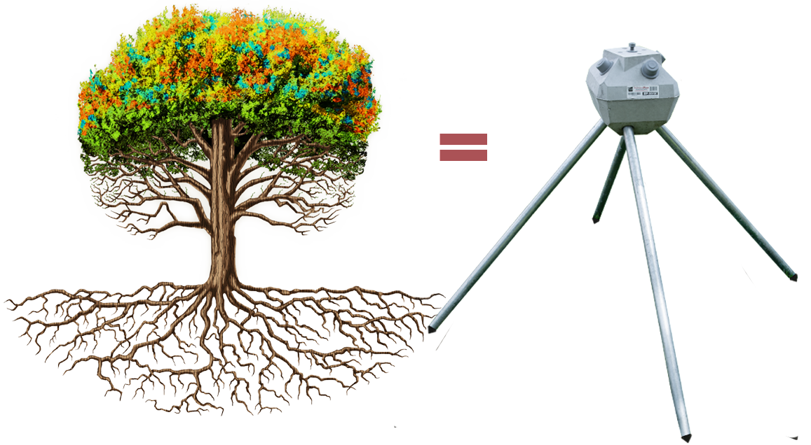
Emulating Nature's Perfect Design
- Like tree roots, Spread Pile Engineering transfers the load of your project to a greater area of soil below. The pins lock, preventing the head from moving up and down.
- Uplift resistance forces frost heaved soils to cleave around the head.
- Bearing forces spread out in an A-shaped cone distributing load over a greater area of undisturbed soils
Diamond Pier Equivalency
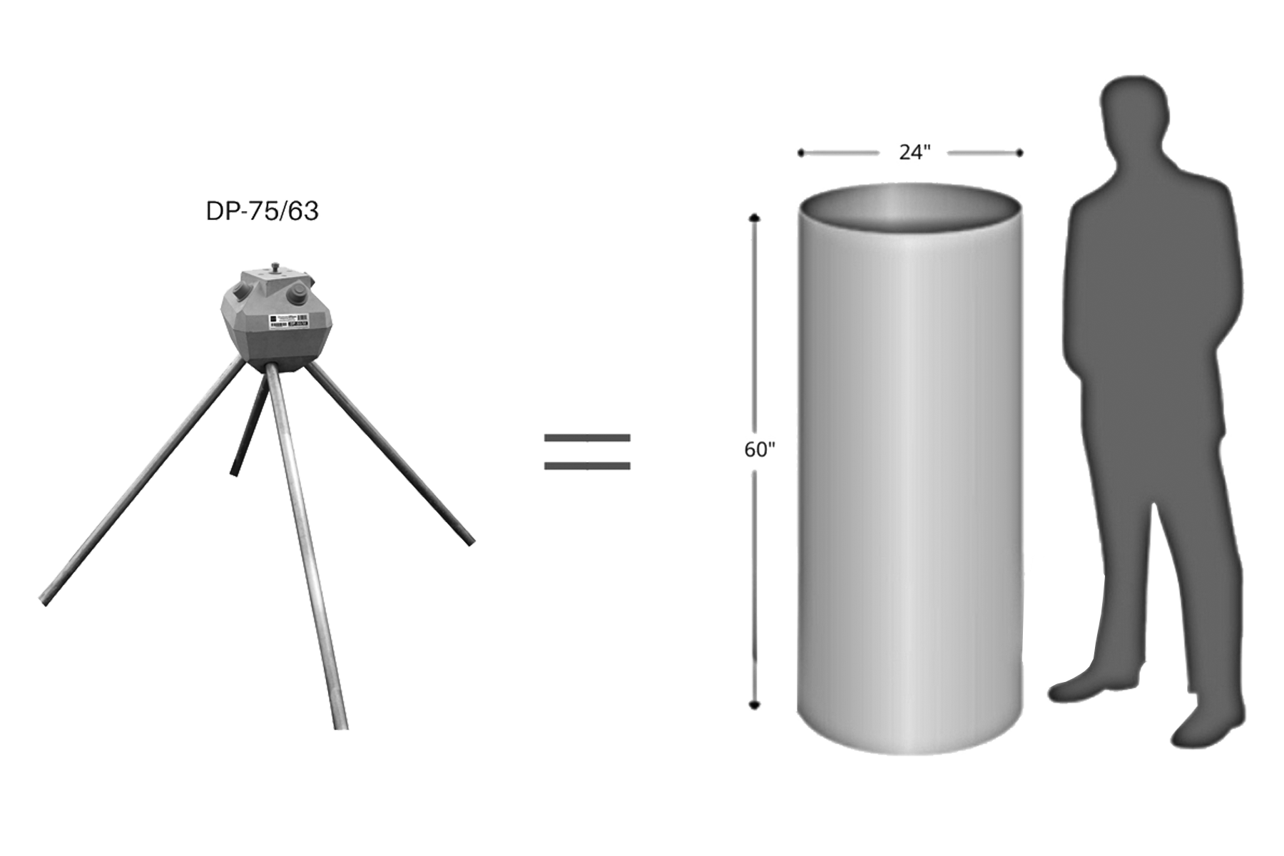
Diamond Pier footings are an equivalent alternative to traditional concrete piers.
DP-50/50 = A Diamond Pier DP-50/50 will support up to the same load as a 20" x 48" traditional concrete footing in 2000 psi soils.
DP-75/63 = A Diamond Pier DP-75/63 will support up to the same load as a 24" x 60" traditional concrete footing in 2000 psi soils.
See the Diamond Pier Load Chart for a full look at Diamond Pier's Equivalency.
RESIDENTIAL DIAMOND PIER LOAD CHART
IAS-Accredited Third-Party Bearing, Uplift, and Lateral Field Tests2
| Model / Pin No. / Length | Bearing Load Capacity | □Equivalent Base Area | ◯Cylinder Comparison | ❄Frost Zone | Uplift Load Capacity | Lateral Load Capacity |
|---|---|---|---|---|---|---|
| DP-50/36” | 2700# | 1.8 sf | 18” dia | 24” | 600# | 600# |
| DP-50/42” | * 3000# | 2.0 sf | 19” dia | 36” | * 900# | * 600# |
| DP-50/50” | 3300# | 2.2 sf | 20” dia | 48” | 1200# | 600# |
| DP-75/50” | * 3750# | 2.5 sf | 21” dia | 48” | * 1400# | * 600# |
| DP-75/63” | 4200# | 2.8 sf | 22” dia | 60” | 1600# | 600# |
| Model / Pin No. / Length | Bearing Load Capacity | □Equivalent Base Area | ◯Cylinder Comparison | ❄Frost Zone | Uplift Load Capacity | Lateral Load Capacity |
|---|---|---|---|---|---|---|
| DP-50/36” | 3600# | 1.8 sf | 18” dia | 24” | 600# | 600# |
| DP-50/42” | * 4000# | 2.0 sf | 19” dia | 36” | * 900# | * 600# |
| DP-50/50” | 4400# | 2.2 sf | 20” dia | 48” | 1200# | 600# |
| DP-75/50” | * 5600# | 2.8 sf | 22” dia | 48” | * 1400# | * 600# |
| DP-75/63” | 6400# | 3.2 sf | 24” dia | 60” | 1600# | 600# |
*Interpolated from field test values.
Notes:
- This load chart is intended for simple structures supported by columns, posts, and beams loaded up to, but not exceeding, the stated capacities. It is not intended for structures with asymmetrical, rotational, overturning, or dynamic forces. Intended uses are described in section 2.0 of ICC-ES prescriptive bearing evaluation report ESR-1895. For projects that exceed the capacities or limitations defined herein, or the intended uses described in ESR-1895, contact PFI for additional information or site-specific capacity evaluation. See also the Use and Applications download at www.diamondpiers.com.
- Capacities shown are tested to a Factor of Safety of 2, and are applicable in properly drained, normal sound soils only, with minimum soil bearing capacities as indicated. Copies of the field test reports are available from PFI upon request.
- See IRC Table R401.4.1, “Presumptive Load-Bearing Values of Foundation Materials,” for a full description of applicable 1500 psf and 2000 psf soil types. For soils below 1500 psf, or soils with unknown characteristics, additional site and design analysis is required. For soils above 2000 psf, the values in this chart shall apply.
- All capacities use four pins of the specified length per foundation. Pin length includes that portion of the pin embedded within the concrete head. See “Check Your Layout” in the Diamond Pier Installation Manual for more information on pin/pier layout and spacing restrictions.
- For professional engineers designing for short-term transient loads, contact PFI for further information.
The Diamond Pier Foundation
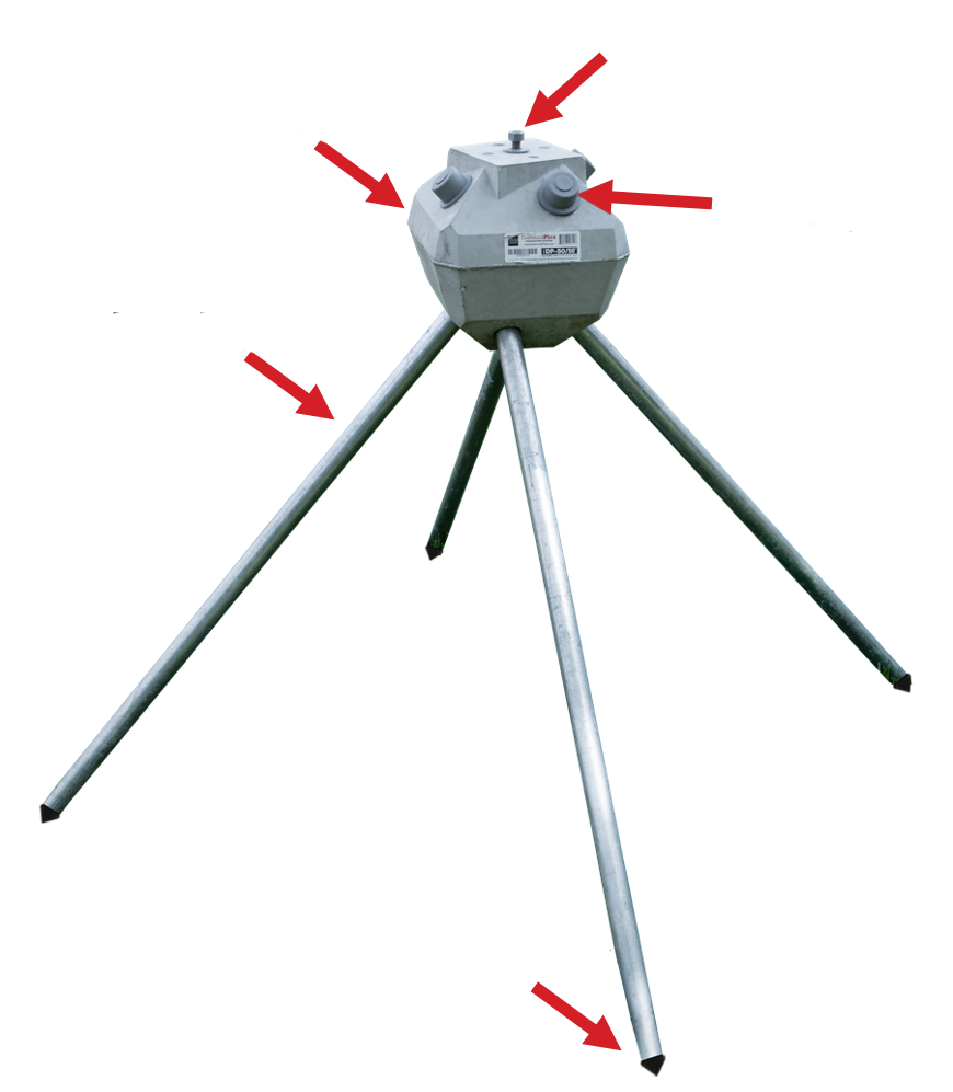
PFI’s innovation is to bring pin pile technology into common use with a superior connector—the Diamond Pier concrete head. This high-strength, precast component is a driving guide, a pin piling lock, and a structural connection all in one.
As a driving guide, the pier maintains the pin angles so that their capacity is definable and consistent. As a lock, the pier is designed to increase its grip on the pin cluster when loaded up, down, or side- ways—getting stronger and tighter as loads increase. And as a connection, an embedded anchor bolt and precast, post-matching shape make it a simple and proportional complement to its supported structure.
The Diamond Pier provides a solid, stable, economical foundation that both captures and preserves the supporting strength and natural functions of the Earth’s soil and, in turn, solidly and simply connects to and protects the permanent structures above.