Installation
Identify and Mark Location
1. Identify where you would like the center of the pier anchor bolt to be located. 2. Mark the location by using reference points that will easily identify the center location of the pier even after top soil is removed. Tip: Set a string line centered on the anchor bolt approximately 12-14" above the ground for a quick reference point and to maintain alignment.
Set the Concrete Head
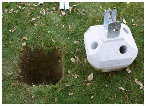
Dig a tapered square hole the same size and shape as the bottom half of the concrete head (see Figure 5). This creates a cradle to steady the head for leveling. Soils directly below the head should be left loose.
Following safe lifting procedures, carefully lift the concrete head and position it in the hole to its midpoint.* Ensure top is level and centered on your alignment.
Replace some of the removed soils back around the sides of the head at grade, lightly tamping to maintain level and alignment during pin driving. (See Notes under “Drive in the Pins” on page 12.) A few inches of small rounded pea gravel may be used if native soils are not available.
NOTE: The edges of the top of the concrete head do not have to align exactly with the sides of the post or post bracket as long as the bracket being used is fully supported by the concrete and providing proper weight distribution.
*The concrete head may also be buried for aesthetic considerations, but access to the top of the head needs to be maintained. Concrete slabs, patios, and other products installed MUST NOT interfere with the Diamond Pier foundation and the attached post/beam assembly. Expansion joints may be used to protect the foundation. Proper drainage must also be maintained.
Drive in the Pins
WARNING: Verify locations of any buried utilities before driving pins (see “Locate Buried Utilities,” page 8).
NOTE: Do not use the pin driving bit as a hammering tool or hammer against it with the sledgehammer. It is to be used with the automatic hammer only.
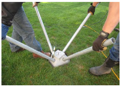
Slide the ends of the pins with the inspection plugs through opposing holes in the concrete head, making sure to support them so their weight does not roll the head out of the hole or out of alignment.
Keeping the pin centered in the driving hole, carefully set each pin 6" to 12" into the soil tapping with the sledgehammer (gripped just below the hammer head) until the concrete head is locked into a level position (see Figure 6). Impact the pin end squarely to minimize flaking of the concrete surface or deformation of the end of the pin (see Note 1).
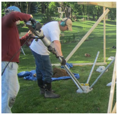
With the pin driving bit installed on the automatic hammer, and another crew member holding the pin, drive in opposing pins alternately in increments (see Note 2). Periodically check for alignment and level (a 5-degree tolerance is allowed). Be sure to keep the weight of the auto-hammer from forcing the pin against the lower half of the driving hole and impacting the concrete head. The other crew member should hold the pin centered in the driving hole (see Figure 7). This will also reduce pin vibration and minimize concrete flaking.
Temporarily drive all pins down to within 6" from the top of the head; this allows easier removal if an obstruction is encountered (see Note 3).
Finish driving the pins with the automatic hammer (with pin driving bit), being careful not to damage the precast concrete head or the upper ends of the pins and leaving approximately 3/4" of the pin protruding from the top of the concrete.
Note 1: Do not attempt to drive the pins all the way down with just the sledgehammer; this may damage the ends of the pins or crack the concrete head.
Note 2: Do not drive a pin all the way down at once as this may cause the head to be pulled to one side. Continue to rotate around the head, driving the pins in increments, until the growing strength in the pile group is sufficient to allow final driving.
Note 3: Do not continue to hammer away at a pin that is bouncing, rattling, or scraping against an impassable object. This may cause the concrete head to ride up the pin, push the head to one side, or risk eccentrically stressing the head with a pin that is out of line. It could also cause the concrete head to have a structural crack, which would require removal and replacement (see “Concrete Head Integrity” on page 16). If encountering difficulties in the soil, see “Encountering Obstructions” on the next page.
Encountering Obstructions
If a pin stops moving when being driven in, STOP driving the pin. If the obstruction is close enough to the surface, it may be dug up and removed. Once accomplished, recompact the soils with the sledgehammer, and then reset the concrete head.
You can also try to drive the pin past or through the obstruction. Be sure the other pins are at least half way in to stabilize the concrete head and ensure that the head will remain in place before trying to drive the obstructed pin in any further. Put a pencil mark on the pin by the head to indicate if the pin moves. Attempt to drive the obstructed pin with the automatic hammer for approximately 10 to 20 seconds, or give it one or two firm square hits with the sledgehammer, which may drive it past the obstruction. Many small rocks will roll, potentially allowing the pin to move directly past. If the pin begins to move, continue with the automatic hammer, but make sure that it is not being forced out of line. If its trajectory is off, this can cause an eccentric stress on the concrete head and crack it.
If you can remove the pin, you can try removing the soil plug and redriving. Inspection plugs may only be omitted when approved by the building official. With the plug removed and less surface area at the lower end, the pin may drive easier, and not be forced by the angle of the plug past an obstruction, but off its trajectory.
If the trajectory is off or the pin will not go in at all, remove all the pins (see “Removing Pins”), rotate the concrete head around its center alignment, and reinstall to avoid the obstruction. The pier may also be relocated, within the parameters of your structure’s design, if necessary.
Removing Pins
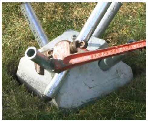
The jacking method is used to spin and pry a pin out from the concrete head simultaneously by using a pipe wrench and a pry bar. This method works best when the pin is approximately 6" extended out from the concrete head. A pipe wrench, a flat bar, and a pry bar are required. Follow the instructions below to turn the pin while corkscrewing it upward. See also the “Pin Removal” video on the website.
Using your right hand, place the pry bar flat against the concrete angle at the outer edge of the pier head and perpendicular to the pin to be removed.
With your left hand, place the pipe wrench on the pin and slide it down tight to the pry bar. The pipe wrench handle should be pointing up slightly and perpendicular to the pry bar to allow the pipe wrench to turn the pin as it is pried (see Figure 8).
Pull up on the pipe wrench handle to lock.
Pull up on the pry bar with your right hand to move the pin out approximately 1" to 2".
Slide the pry bar back to be flush with the concrete angle on the pier head.
Repeat lock and jack (steps 3–5) until the pin can be pulled out by hand.
Note 1: For the first 4" of removal use the flat bar with the pipe wrench. After the pin is 4" removed you may use a pin as a pry bar.
Note 2: For an alternate removal technique, an internal pipe locking tool with an electric impact wrench may be used to spin the pin and draw it from the concrete head.
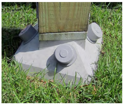
Place Pin Caps on Pins
Set the pin caps loosely on the ends of the pins so they can be removed for pin length inspection (see “Pin Length Inspection,” page 16).
Set brackets and posts or beams, and frame and complete the supported structure.
Once these framing material loads have been applied, pull the caps off and reverify the extent of the protruding pins, adjusting as necessary by tapping with the small sledgehammer.
After the field inspection has been completed, tap the caps down tight with the small hammer (see Figure 9) to seal them against the concrete.
NOTE: If the caps will not go on, check the pin ends for any extreme deformations that may have occurred while driving. File or grind off any damage to re-establish the original diameter, and apply the cap.
Jump to Installation Manual Section: